555 Timer Schematic / The 555 timer schematic diagram | Download Scientific Diagram - The 555 timer is a chip that can be us…. This pin connects to the negative side of the battery. This will help you instantly recognise the function of each pin: 555 datasheet 555 duty cycle 555 metronome 555 reset function 555 time delay relay inverted 555 timer pulse generator. Resistive network consists of three equal resistors and acts as a voltage divider. Also, 555 timer is used to generate an oscillating pulse.
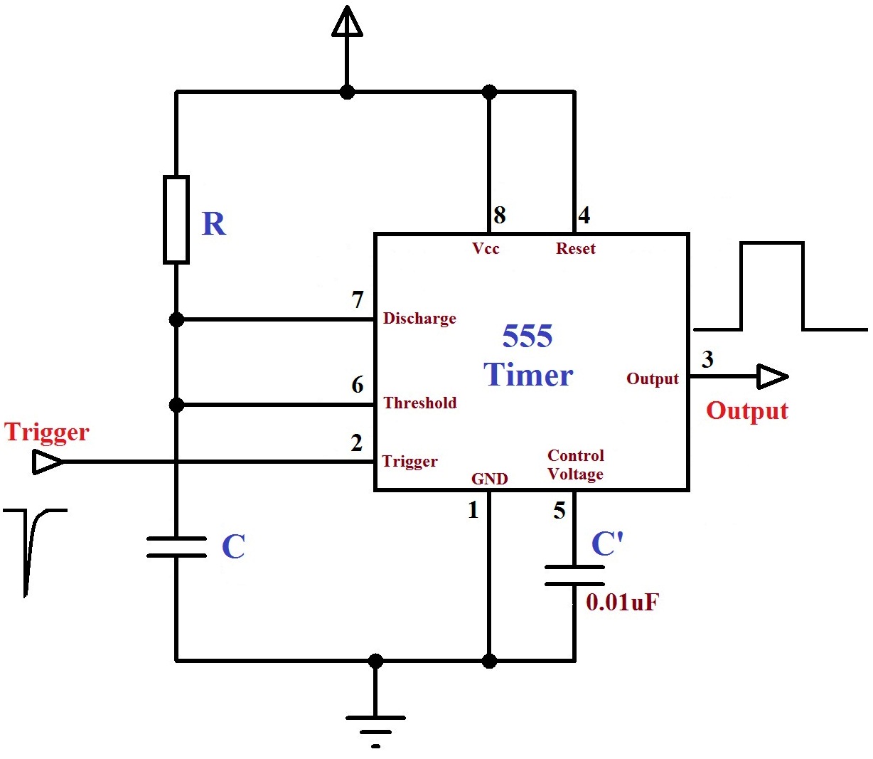
555 timer was first introduced by signetics corporation in 1971 as se555/ne555. Figure 2 shows the basic 555 timer monostable circuit. This low pulse lasts for 71.66 ms, giving a duty cycle of 99.53%. Simple 555 timer circuits & projects. We connect a 100μf capacitor to the positive voltage supply and then to pin 2.
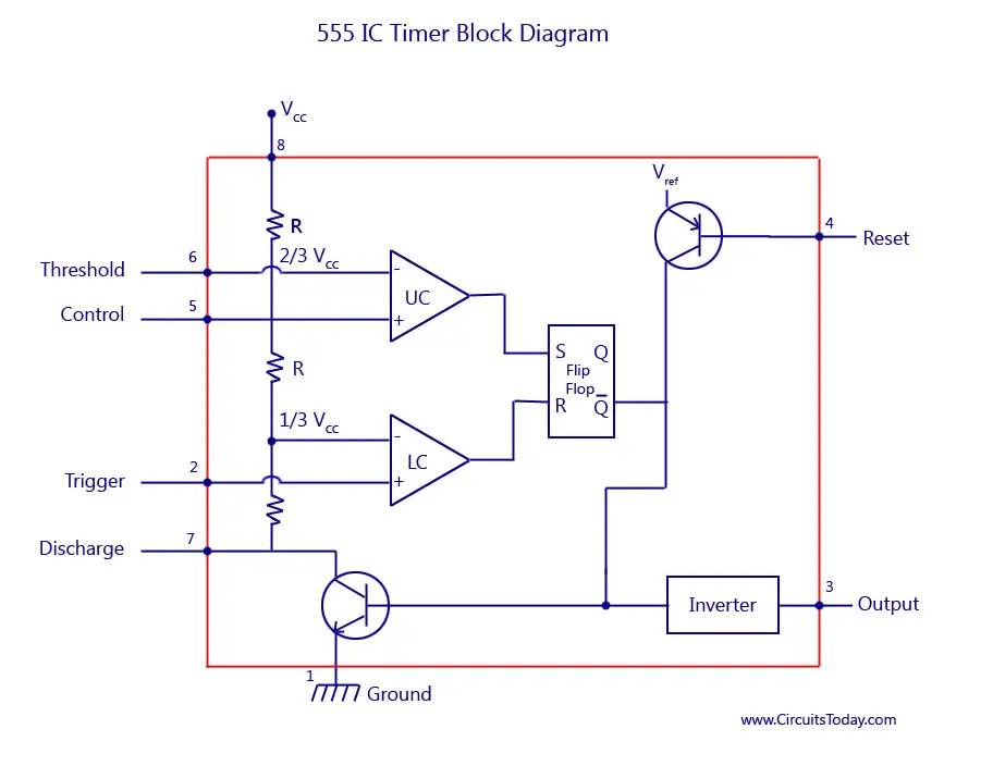
555 Timer IC-Block Diagram-Working-Pin Out Configuration ... from www.circuitstoday.com The 555 can be used to provide time delays, as an oscillator, and as a flip flop element. In 2017, it was said over a billion 555 timers are produced. The ic can operate in three different modes such as astable, monotstable and bistable, because of which it can be adapted into many types of circuit designs like time delay circuits, pulse generation circuit, oscillator circuit and much more. Basic 555 monostable multivibrator circuit. Being an integral part of electronics project, 555 timer ic is very often used in simple to complex electronics projects. Adjustable on off timer(using 555 astable mode) in this circuit a timer with cyclic on off operations is designed. The second 555 timer helper will extend the timers output duration without having to use large values of r1 and/or c1. Connects to the 0v power supply.
555 timer was first introduced by signetics corporation in 1971 as se555/ne555.
The second 555 timer helper will extend the timers output duration without having to use large values of r1 and/or c1. In 2017, it was said over a billion 555 timers are produced. In this project, we are using 555 timer ic to create various timer circuit like 1 min timer circuit, 5 min timer circuit, 10 min timer circuit, and 15 min timer circuit. This low pulse lasts for 71.66 ms, giving a duty cycle of 99.53%. 555 timer ic is an integrated circuit used in a variety of timer, pulse generation circuit, and oscillator circuit applications. 555 datasheet 555 duty cycle 555 metronome 555 reset function 555 time delay relay inverted 555 timer pulse generator. This circuit is part of this chips datasheet, complete with the math needed to design to specification, and is one of the reasons a 555 is referred to as a timer. As discussed in the above section, the ic is in its standard monostable mode. Daman shah june 5, 2021. As we know 555 timer ic is one of the commonly used ic among students and hobbyists. Adjustable on off timer(using 555 astable mode) in this circuit a timer with cyclic on off operations is designed. 555 timer is an industrial standard ic existing from early days of ic. An arduino microcontroller is used to demonstrate usage.
555 timer circuits (133) browse through a total of 133 555 timer circuits and projects including the timer's datasheet. 500ms is the same as saying 0.5s so by rearranging the formula above, we get the calculated value for the resistor, r as: In this category, we have handpicked some really useful 555 timer circuits which will be interesting to electronics engineering students and hobbyists alike. As discussed in the above section, the ic is in its standard monostable mode. The 555 ic timer circuit above shows a very straightforward design where the ic 555 forms the central controlling part of the circuit.
555 Timer IC Electronic Circuit Astable Multivibrator ... from img.favpng.com As discussed in the above section, the ic is in its standard monostable mode. The 555 timer is a chip that can be us… Timer, op amp, and optoelectronic circuits & projects. The values of r1 and c1 determine how long the output will remain high. This circuit uses very basic components like 555 timer and 4017 counter. 555 timer is an industrial standard ic existing from early days of ic. With this information you will learn how how the 555 works and will have the experience to build some of the circuits below. Here is the practical demonstration of the bistable mode of 555 timer ic, where we have connected a led to the output of the 555 ic.
The above schematic shows the 555 timer bistable multivibrator circuit.
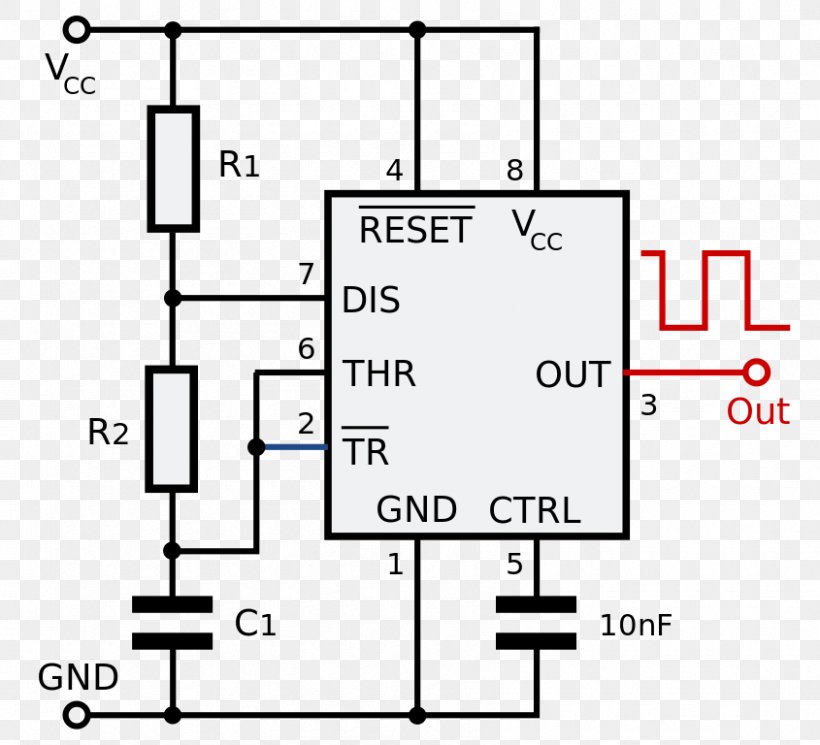
We have seen in the last few tutorials that the 555 timer can be configured with externally connected components as multivibrators, oscillators and timers, with timing intervals ranging from a few microseconds to many hours. In this mode, the circuit of the ic 555 timer produces the continuous pulses with exact frequency primarily based on the value of the two resistors and. Once this switch is pushed, the circuit pulls its output to a. Being an integral part of electronics project, 555 timer ic is very often used in simple to complex electronics projects. These on off intervals can be adjusted by varying the 555 timer output and number of counter outputs. 555 timer was first introduced by signetics corporation in 1971 as se555/ne555. The standard 555 timer ic is made of 2 diodes. This led will be switched on when button s1 is pressed and switched off when button s2 is pressed. The second 555 timer helper will extend the timers output duration without having to use large values of r1 and/or c1. There are simple circuits for beginners and advanced engineers. The working modes of a 555 timer are astable, bistable, and monostable. 500ms is the same as saying 0.5s so by rearranging the formula above, we get the calculated value for the resistor, r as: Referring to the timing diagram in figure 3, a low voltage pulse applied to the trigger input (pin 2) causes the output voltage at pin 3 to go from low to high.
The 555 is also very versatile, and can be used. 555 datasheet 555 duty cycle 555 metronome 555 reset function 555 time delay relay inverted 555 timer pulse generator. How to use the 555 timer as a monostable multivibrator. The output voltage from the chip is around 1.5 v lower than vcc when high and around 0 v when low. Each mode of operation indicates a circuit diagram and its output.
Monstable Multivibrator using 555 Timer from electrosome.com Resistive network consists of three equal resistors and acts as a voltage divider. For a great resource on the 555 timer, opamps, and other ic's check out the engineer's mini notebook: We have a large collection of simple and advanced projects using 555 timer ic. The values of r1 and c1 determine how long the output will remain high. 555 timer helpers schematic the addition of a capacitor to the trigger will not work for short output pulses as there is also a short delay in the recovery of the trigger terminal voltage. This circuit uses very basic components like 555 timer and 4017 counter. 555 timer was first introduced by signetics corporation in 1971 as se555/ne555. Using the 555 timer ic in special or unusual circuits.
Using the 555 timer ic in special or unusual circuits.
555 datasheet 555 duty cycle 555 metronome 555 reset function 555 time delay relay inverted 555 timer pulse generator. Its name is derived from three 5k ohm resistors ,connected in series used in it.the timer ic can produce required waveform accurately. Lm555 timer 1 features 3 description the lm555 is a highly stable device for generating 1• direct replacement for se555/ne555 accurate time delays or oscillation. The ic can operate in three different modes such as astable, monotstable and bistable, because of which it can be adapted into many types of circuit designs like time delay circuits, pulse generation circuit, oscillator circuit and much more. Let us discuss in detail about this circuit. Adjustable on off timer(using 555 astable mode) in this circuit a timer with cyclic on off operations is designed. Being an integral part of electronics project, 555 timer ic is very often used in simple to complex electronics projects. The breadboard schematic of the above circuit is shown below. Basic 555 monostable multivibrator circuit. As discussed in the above section, the ic is in its standard monostable mode. How to use the 555 timer as a monostable multivibrator. We have seen in the last few tutorials that the 555 timer can be configured with externally connected components as multivibrators, oscillators and timers, with timing intervals ranging from a few microseconds to many hours. Also, 555 timer is used to generate an oscillating pulse.